What Are the Top Types of RF Cable Assemblies?
RF cable assemblies carry radio-frequency signals between antennas, radios, instruments, and other connected equipment. They may look like simple cables with connectors, but their construction affects signal loss, shielding, durability, and handling. A cable that works well on a bench may be a poor fit inside a moving enclosure or outdoor installation. Small details matter. Impedance, operating frequency, connector type, cable length, bend radius, and exposure to heat or moisture all shape selection. These factors deserve attention before comparing product labels.
The phrase “top types” can refer to several practical categories, not one universal ranking. Common options include flexible coaxial assemblies, low-loss cables for longer runs, semi-rigid assemblies for compact layouts, and phase-stable designs for measurement systems. There are also miniature assemblies for crowded devices and ruggedized versions for demanding environments. Each type solves a different problem. Yet the categories can overlap, and a premium cable is not automatically the right cable. That point is easy to miss. This guide outlines the main RF cable assembly types, explains where each is commonly used, and highlights the specifications worth checking. It also notes trade-offs, such as flexibility versus shielding or low loss versus cost. Actual performance depends on the complete assembly and its installation, so verify manufacturer data and test requirements before choosing. No single specification tells the whole story.
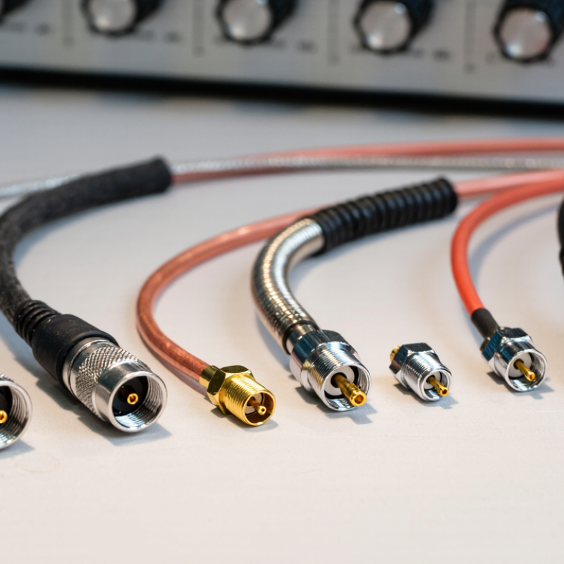
RF Cable Assemblies: 50 Ω Coaxial Interfaces and Key Selection Criteria
RF cable assemblies connect radios, antennas, test equipment, and other high-frequency components. In many RF systems, 50 Ω coaxial interfaces are the standard. Matching the cable and connectors to the equipment helps limit reflections and signal loss. Common assembly types include flexible coax for moving or crowded installations, semi-rigid coax for stable internal routing, and phase-stable cable for measurements where repeatable phase matters. Small details matter.
Selection starts with the operating frequency and required cable length. Check insertion loss across the full frequency range, not just at one point. Return loss or VSWR can indicate how well the assembly maintains impedance. Connector type, shielding, and power handling also affect performance. A 50 Ω label alone is not enough; confirm that both mating interfaces and the cable specification suit the equipment.
Physical conditions matter just as much. Measure the route, allow the cable’s minimum bend radius, and consider temperature, vibration, and repeated movement. A datasheet can make the choice look cleaner than it is; real routing adds bends, strain, and awkward access. For a test bench, flexibility may be useful. For fixed equipment, a more stable assembly may fit better. The trade-off is not always obvious.
What Are the Top Types of RF Cable Assemblies?
Representative upper frequency ratings for common 50 Ω coaxial connector interfaces
These values are typical interface ratings, not guarantees for every cable assembly; actual limits depend on the connector design, cable, and assembly. When selecting an assembly, consider operating frequency alongside insertion loss, length, power handling, flexibility, and environmental requirements.
SMA Assemblies: Standard Designs Reach 18 GHz; Precision Types 26.5 GHz
SMA cable assemblies remain common in RF test benches, antennas, and compact instruments. Standard designs are typically rated to 18 GHz, while precision SMA assemblies can reach 26.5 GHz. That difference matters near the upper band edge. At 26.5 GHz, small changes in connector geometry, cable condition, or mating torque can affect measured results. IEC 60169-15 defines the SMA interface, while IEEE Std 287 provides guidance for precision coaxial connector performance. These references help engineers compare interfaces and measurement expectations; they do not guarantee that every assembled cable will meet the same frequency rating.
A frequency number is only part of the selection. Check insertion loss, return loss, phase stability, and power handling across the intended band. Ask for a test report tied to the exact cable length and connector configuration. For example, a 30 cm assembly used at 24 GHz may behave differently from a shorter lead, especially after repeated bending. I would not assume “precision” means immune to handling errors. It does not.
Tips: Keep mating surfaces clean, use a calibrated torque wrench, and avoid twisting the cable while tightening. Verify the assembly with a calibrated vector network analyzer when measurement accuracy matters. Inspect it again after repeated flexing.
N-Type Assemblies: 50 Ω Interfaces Commonly Rated to 11 GHz
N-Type RF cable assemblies suit many fixed links because their threaded coupling resists loosening during routine handling.
The 50 Ω interface is widely used in test equipment, antennas, and communications systems. IEC 61169-16:2013 specifies Type N connector requirements and a standardized frequency range extending to 11 GHz. That figure describes the connector interface, not every cable assembly. Cable type, length, and termination quality still affect measured performance. Small details matter.
At higher frequencies, even a small impedance mismatch can increase reflected energy. For a practical check, inspect the assembly’s specified frequency range, insertion loss, and return loss, then verify the mated connectors are clean and fully tightened. A short jumper on a bench may behave well, while a longer run can show more loss. The 11 GHz rating alone cannot predict that difference. I would also confirm the test setup is calibrated; otherwise, the connector may get blamed for an error elsewhere. IEC data offers a useful baseline, but actual results depend on the full assembly and its installation. Not automatically.
BNC and TNC Assemblies: Typical Frequency Ratings of 4 GHz and 11 GHz
BNC and TNC assemblies are common choices when a compact coaxial connection is needed. Typical published upper-frequency ratings are about 4 GHz for BNC and 11 GHz for TNC. IEC 61169-8 and IEC 61169-17 specify interface requirements for these connector types, but a standard interface does not guarantee every finished cable assembly reaches its typical rating. That distinction matters.
At 4 GHz, a BNC assembly may suit many bench instruments and lower-frequency signal paths. TNC’s threaded coupling can help maintain a stable connection under vibration, while its typical 11 GHz rating extends its useful range. Yet the connector is only one part of the system. Cable type, length, termination quality, and bend radius can all affect insertion loss and return loss. A sharply bent cable behind a panel can undermine an otherwise capable connector.
Check the assembly’s frequency sweep data, not just the connector label. Ask for measured insertion loss and VSWR across the intended band, and confirm the test configuration. Ratings vary by design. The headline number can be a little too neat. A real installation deserves a real measurement.
What Are the Top Types of RF Cable Assemblies? — BNC and TNC Assemblies
| Assembly Type |
Coupling Mechanism |
Common Impedance |
Typical Frequency Rating |
Common Uses |
Key Considerations |
| BNC RF cable assembly |
Bayonet coupling with a quick quarter-turn connection |
50 Ω; 75 Ω versions are also available |
Up to approximately 4 GHz for suitable assemblies |
Test equipment, video and broadcast systems, communications, and general-purpose RF connections |
Fast to connect and disconnect. Confirm the impedance and frequency rating, especially for 75 Ω video systems. |
| TNC RF cable assembly |
Threaded coupling that provides a more secure connection |
Most commonly 50 Ω; some 75 Ω versions are available |
Up to approximately 11 GHz for suitable assemblies |
Mobile radio, antenna feeds, outdoor equipment, and applications needing a more vibration-resistant connection |
The threaded interface helps resist loosening from vibration. Check the specified operating range and environmental requirements. |
Note: Frequency ratings are typical reference values, not guarantees for every assembly. Actual performance depends on the connector design, cable, assembly workmanship, impedance match, and test conditions; the lowest-rated component limits the complete assembly.
SMB Assemblies: Compact Push-On Interfaces Commonly Rated to 4 GHz
SMB cable assemblies suit compact RF layouts where space and quick access matter. Their push-on coupling lets a technician connect them without turning a threaded nut. The interface is small, yet it can support stable signal paths in test fixtures, instruments, and communication equipment.
Many SMB assemblies are specified for operation up to 4 GHz. Treat that figure as a product rating, not a guarantee for every setup. Impedance, cable type, connector condition, and assembly quality all affect performance. At higher frequencies, a poorly routed cable or loose fit can contribute to signal loss. The convenience has a trade-off: push-on connections may be less resistant to repeated movement than threaded interfaces. This detail is easy to overlook.
Tips: Check the assembly’s frequency and impedance specifications before ordering. Inspect the connector faces for dirt or damage, then push the halves together straight. Avoid pulling the cable to disconnect it. Leave room for the cable’s recommended bend radius; tight bends near the connector can stress the joint. A quick fit is helpful, but it should not replace careful handling.