What Are the Top Types of Fiber Optic Connectors?
Fiber optic connectors are small, but their fit can affect an entire network link. A loose connection, dirty end face, or mismatched polish may increase signal loss. The right choice depends on equipment, fiber type, available space, and how often technicians need to disconnect the link. Small details matter.
Common options include SC, LC, ST, FC, and MPO/MTP connectors. SC connectors use a push-pull coupling and are easy to handle. LC connectors have a smaller form, so they suit dense patch panels and switches. ST connectors lock with a bayonet twist, while FC connectors use a threaded body that resists accidental movement. MPO/MTP connectors join multiple fibers in one interface, making them useful for high-density cabling. Each design solves a different problem; none is automatically best.
Fiber Optic Association founder Jim Hayes is a recognized fiber-optics educator. A practical paraphrase of his guidance is: “Choose connectors for the link’s requirements, then inspect and clean them before connection.” This is not a verbatim quotation, but it reflects sound field practice. Even experienced technicians can overlook a contaminated end face. A quick inspection can prevent avoidable troubleshooting.
This guide compares the leading connector types, their coupling styles, and common applications. It also explains key details such as polish, insertion loss, and compatibility. Those details matter more than appearance. Product naming can be confusing, and connector choice alone cannot guarantee link performance. Proper installation and testing still count.
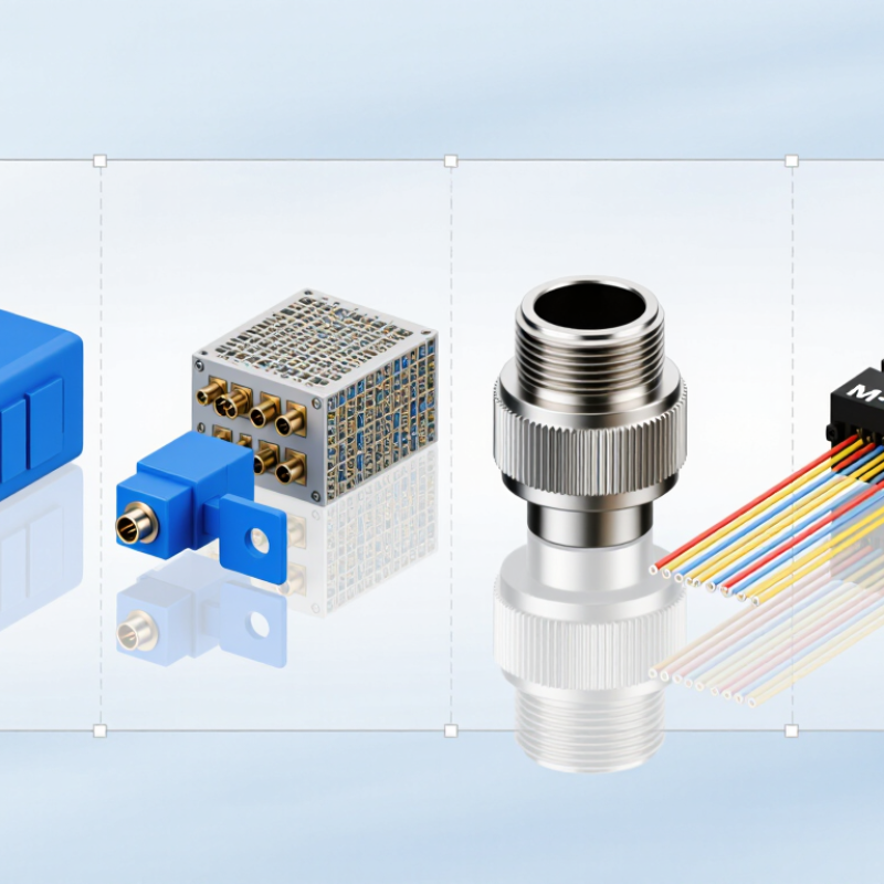
How Fiber Optic Connectors Are Classified
Fiber optic connectors are best classified by interface, fiber type, endface geometry, and termination method.
Interface families such as LC, SC, ST, FC, and MPO describe how connectors mate and how many fibers they carry. An LC connector has a compact latch; an MPO connector aligns multiple fibers in one ferrule. IEC 61754 documents connector interface dimensions, helping technicians check compatibility rather than relying on appearance alone. Small differences matter.
Fiber type is another practical distinction. The Fiber Optic Association’s technical reference describes common multimode core diameters of 50 or 62.5 micrometers, while single-mode cores are typically about 8–10 micrometers. Endfaces are commonly polished as UPC or APC; the angled APC surface can reduce back reflection, but the two polish types should not be mated together. Termination may be factory-finished or performed in the field, with performance depending on inspection and workmanship. This taxonomy is useful, but not perfect: connector names can describe shape, while the same shape may serve different fiber and polish combinations. A label alone is not enough. Check the equipment interface, fiber specification, and endface before connection.
LC Connectors: Compact Interfaces for High-Density Links
LC connectors are popular where rack space is tight. Their 1.25 mm ferrules are half the diameter of the 2.5 mm ferrules used in SC connectors, allowing more ports on a panel. The IEC 61754-20 standard defines the LC connector interface, giving technicians a consistent reference for mating hardware. In a crowded cabinet, that compact footprint can mean shorter patching paths and clearer port layouts. Small parts, real consequences.
The density advantage is useful in data centers and telecom rooms, but it does not guarantee better performance by itself. The Fiber Optic Association’s technical guidance emphasizes inspection and cleaning because dust on a connector end face can increase signal loss. That matters with LC plugs: their small ferrules are easy to touch while handling, and the latch can be awkward to release when ports sit close together. Duplex LC connectors also help organize transmit and receive fibers in pairs. Check polarity before installation, then verify the link with suitable test equipment. A neat panel can still hide a faulty connection. I have seen compact layouts save space yet make maintenance harder when labels are cramped; density needs room for hands, too.
SC and ST Connectors: Push-Pull and Bayonet Designs
What Are the Top Types of Fiber Optic Connectors?
SC and ST Connectors: Push-Pull and Bayonet Designs
SC connectors use a square body and push-pull coupling. Installers can seat or remove them with a straight motion, which helps in crowded panels. Their keyed design also limits incorrect alignment. IEC 61754-4 specifies the SC interface. The FOA Reference Guide to Fiber Optics gives about 0.3 dB as a typical connector-loss benchmark; actual results depend on cleanliness, alignment, and inspection. Small details matter.
ST connectors have a round body and bayonet coupling. A quarter-turn locks the connector, helping it stay seated when a cable is disturbed. IEC 61754-2 specifies the ST interface. In practice, the twist can feel secure, but it also takes room to operate. That can be awkward in a tightly packed rack. Both connector types are used with single-mode and multimode fiber, subject to the equipment and cable specifications. For either type, inspect and clean the end face before mating; dust can raise insertion loss or cause inconsistent readings. The connector shape alone does not guarantee a good link. Verify loss with an appropriate test rather than assuming the connection is sound.
What Are the Top Types of Fiber Optic Connectors? — SC and ST Connectors: Push-Pull and Bayonet Designs
| Feature |
SC Connector |
ST Connector |
| Coupling design |
Push-pull latch: push to connect and pull the housing to disconnect. |
Bayonet coupling: insert the connector and turn it to lock; reverse the turn to release. |
| Connector shape |
Typically has a square outer body. |
Typically has a round metal or metal-style outer body. |
| Ferrule size |
Uses a 2.5 mm ferrule. |
Uses a 2.5 mm ferrule. |
| Common formats |
Available in simplex and duplex configurations. |
Commonly found in simplex configurations. |
| Fiber compatibility |
Available for single-mode and multimode fiber, depending on the connector and polish type. |
Available for single-mode and multimode fiber, depending on the connector and polish type. |
| Typical use |
Used in fiber-optic communications and data-network connections, including many patch-panel and equipment interfaces. |
Often encountered in older premises networks, test setups, and installations that use bayonet-style interfaces. |
| Installation consideration |
Check that the latch is fully engaged and that the connector and adapter are correctly aligned. |
Align the connector, insert it fully, and turn until the bayonet mechanism locks securely. |
| Selection tip |
Choose SC when the equipment or adapter panel specifies an SC interface and the push-pull format suits the installation. |
Choose ST when the equipment or adapter panel specifies an ST interface; verify that the bayonet coupling is compatible. |
Note: Optical performance depends on the connector’s fiber type, polish, condition, and installation quality. Always match the connector to the equipment and adapter interface.
FC Connectors: Threaded Interfaces for Secure Connections
FC connectors use a threaded coupling rather than a push-pull latch. The sleeve screws into place, helping resist accidental release when a cable is tugged or equipment vibrates. That makes FC useful in test benches, instrumentation, and other fixed connections. The fit feels deliberate.
The IEC 61754-13 interface standard defines the FC connector family. For performance context, IEC 61755-3-1 sets a maximum attenuation of 0.25 dB for Grade B qualifying single-mode connector interfaces. That figure is a standardized test limit, not a promise for every installed FC connection. End-face cleanliness, alignment, and mating quality still matter. A small dust particle can cause measurable loss.
Threading also has a trade-off. Technicians need extra time to screw and unscrew each connection, and overtightening can complicate handling. In practice, hand-tightening is usually sufficient; inspect and clean the end face before mating. I would not treat the secure feel as proof of a clean connection. Use an optical loss test when link performance matters.
MPO/MTP Connectors: Multi-Fiber Interfaces for High-Capacity Networks
What Are the Top Types of Fiber Optic Connectors?
MPO multi-fiber connectors bring several optical fibers together in one compact interface. This design supports high-capacity networks where rack space and installation time matter. Depending on the configuration, a connector may carry 8, 12, or 24 fibers. It can link trunk cables between data-center cabinets or connect equipment built for parallel optical transmission. One plug, many paths.
That density comes with details worth checking. Fiber count, connector keying, and polarity must match across the link. A mismatch can leave channels dark, even when the connector appears securely seated. End-face cleanliness also matters; a tiny speck can disrupt several channels at once. In practice, inspection and cleaning should happen before connection, not after troubleshooting begins. Planning can still feel awkward when older cabling must fit a newer layout.
Tips: Label both ends clearly, verify polarity, and inspect the end face before mating connectors. Keep unused ports capped. Small checks help prevent larger delays.
For high-density links, MPO connections can reduce the number of individual patch cords and simplify cable routing. But fewer cables do not always mean simpler maintenance. Technicians need a clear fiber map and compatible test equipment to identify each channel. Choose the connector arrangement to suit the network design, and document changes as they happen. Even a tidy rack can hide an unexpected polarity issue.