Choosing a coax connector is not a cosmetic decision. It affects impedance continuity, signal loss, shielding, and mechanical reliability. A connector that fits physically may still perform poorly at the system’s frequency or power level. Small details matter: thread condition, cable diameter, contact alignment, and careful termination can change the result.
This guide introduces ten common coax cable connectors, including BNC, SMA, Type N, TNC, F-type, RCA, SMB, MCX, QMA, and UHF. Each serves a different mix of frequency range, durability, size, and installation needs. RF engineer James R. Rautio’s design perspective can be paraphrased this way: “Treat each connector as part of the RF path, not as an accessory.” That is a practical reminder, not a verbatim quotation. Check the cable specification and equipment interface before choosing. Then consider whether the connection will face vibration, frequent mating, or outdoor exposure. The cheapest option may not be the least costly over time. And connector names alone can mislead. Two similar-looking parts may use different interfaces or impedance ratings. A careful match reduces avoidable signal problems, though it cannot fix poor cable routing or installation. Real setups are messier than catalogs suggest. That deserves a second look.
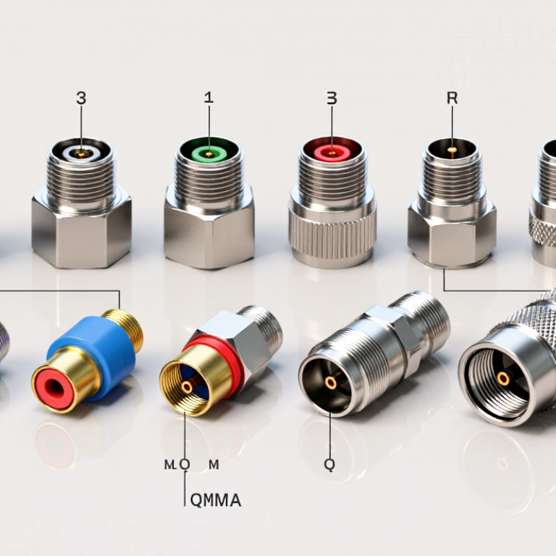
A coaxial connector joins a cable’s center conductor and outer shield to equipment while preserving the cable’s concentric structure. The center contact carries the signal; the outer body connects to the shield, helping limit interference and maintain a continuous return path. The connector does not strengthen a weak signal. A poor fit, damaged contact, or loose shield can instead cause reflections and signal loss.
Two common nominal impedances are 50 ohms and 75 ohms. The right choice depends on the system, not appearance: 50-ohm connections are common in radio-frequency equipment, while 75-ohm connections are widely used for video and broadcast signals. IEC 61169-1:2013 sets general requirements for RF coaxial connectors, including electrical and mechanical performance. These details matter because matching impedance helps reduce reflections; a connector that screws on neatly may still be electrically unsuitable.
Tip: Check the cable and device specifications before choosing a connector. Inspect the center pin and shield contact, then tighten the fitting securely without forcing it. A small mismatch can be easy to overlook, especially when two connectors look nearly identical.
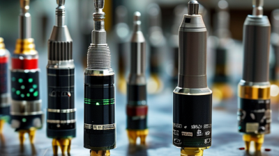
Coaxial connectors are distinguished by more than their shape. Impedance, coupling method, size, and operating frequency all affect where each type fits. BNC connectors use a bayonet lock, making them quick to connect in test setups. F connectors rely on a threaded fit and are common with 75-ohm television cable. Small details matter.
N-type connectors are larger and robust, while SMA connectors are compact and commonly used in higher-frequency equipment. TNC connectors add threads to a design similar to BNC, which can help resist loosening from vibration. UHF connectors are older and comparatively large; their name does not guarantee performance at very high frequencies. Check the specified frequency range, not just the connector label.
Smaller snap-on types, such as SMB and MCX, save space but may be less convenient to handle repeatedly. RCA connectors are easy to recognize, yet they are generally suited to less demanding signal applications. A connector must also match the cable’s impedance and dimensions. For example, pairing a 50-ohm cable with a 75-ohm connector can create signal reflections. In practice, catalog categories can blur: installation quality, adapter use, and cable condition also influence results. A tight fit alone is not proof of a good RF connection.
A comparison of common coupling mechanisms across ten coaxial connector types.
The chart groups BNC as bayonet; TNC, SMA, SMC, N, and F as threaded; SMB, MCX, and MMCX as snap-on; and RCA as push-on. Counts reflect these ten examples and their common coupling styles; specific connector variants may differ.
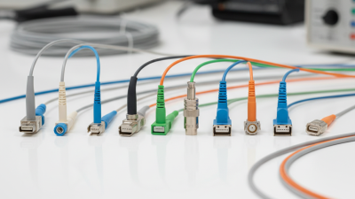
Coaxial connectors differ in impedance, locking style, size, and frequency range. The IEC 61169 series specifies interface requirements and test methods, reminding buyers to check the exact connector specification—not just its name. Small details matter. F connectors are common on 75-ohm television and broadband lines; BNC suits test benches and video equipment, where quick bayonet locking helps. TNC adds a threaded coupling for vibration-prone installations. N connectors often serve outdoor antennas and radio links. SMA supports compact microwave assemblies, while SMB and SMC fit smaller equipment where space is tight.
MCX and MMCX appear in compact receivers, GPS units, and portable instruments; their small push-on fittings are convenient, but repeated handling can loosen connections. The larger 7/16 DIN type is used in high-power cellular and broadcast infrastructure.
Check the cable’s impedance before matching any connector: a 50-ohm radio component and a 75-ohm video component may mate physically yet perform poorly together. IEC 61169 specifications help compare interfaces, but actual frequency limits vary by design. A product sheet matters. I would verify center-pin dimensions, cable compatibility, and return-loss data before ordering; connector names alone are an imperfect guide.
Top 10 Types of Coax Cable Connectors Buyers Should Know
Impedance is a practical starting point. Many radio systems use 50-ohm coax, while video equipment commonly uses 75-ohm cable. Keep the cable and connector impedance matched to reduce reflections and signal loss. A connector may fit physically yet still be the wrong electrical choice. It happens more often than buyers expect.
Frequency rating matters too. As frequency rises, small changes in connector geometry and installation can affect performance. Check the specified operating range for the connector and cable assembly, not just the connector type. Secure, clean mating surfaces help maintain a consistent connection. Even careful selection cannot compensate for poor cable preparation.
Tips: Match impedance, verify frequency limits, and check the environment. For outdoor or damp locations, look for suitable sealing and corrosion resistance. In equipment exposed to vibration, confirm that the connection stays secure. Temperature also matters: materials can expand, contract, or age over time. A detail that seems minor on a bench can become a weak point in the field. One imperfect habit worth reconsidering is choosing by appearance alone; compatibility is not always visible.
| Connector type | Common impedance | Typical frequency capability | Coupling and connection | Environmental considerations | Common applications |
|---|---|---|---|---|---|
| BNC | 50 Ω or 75 Ω | Often used through several GHz; maximum rating varies by version and manufacturer. | Bayonet coupling; quick to connect and disconnect. | Suitable for general indoor use. Outdoor use requires a weather-sealed connector and cable assembly. | Test equipment, video, antennas, and instrumentation. |
| TNC | Most commonly 50 Ω; 75 Ω versions also exist. | Common versions operate into the GHz range; precision and specialized versions can be rated higher. | Threaded coupling provides a more secure connection than a bayonet coupling. | Threading can help resist vibration. Weather resistance depends on sealing and assembly design. | Wireless equipment, antennas, and outdoor RF connections. |
| N | 50 Ω or 75 Ω | Many standard designs are used to about 11 GHz; precision designs may support higher frequencies. | Threaded coupling; relatively large and mechanically robust. | A good option for demanding installations when the complete assembly is properly sealed and rated. | Base-station antennas, radio systems, and test setups. |
| SMA | 50 Ω | Many standard versions are rated to 18 GHz; precision versions may reach 26.5 GHz or more. | Compact threaded coupling; avoid repeated over-tightening or excessive mating cycles. | Typically used in controlled or protected environments unless specifically sealed for outdoor use. | Microwave modules, antennas, and RF test equipment. |
| SMB | 50 Ω or 75 Ω | Commonly used to a few GHz; the exact limit depends on the impedance and connector design. | Snap-on coupling allows fast connection in compact spaces. | Best suited to protected indoor or equipment-enclosure installations. | Internal equipment connections, communications hardware, and instrumentation. |
| SMC | Usually 50 Ω | Common designs are used into several GHz; check the specific part rating for higher-frequency work. | Threaded coupling in a compact format. | Threading helps retain the connection, but environmental sealing must be specified separately. | Compact RF assemblies, communications equipment, and instrumentation. |
| MCX | 50 Ω or 75 Ω | Many designs are rated to approximately 6 GHz; ratings vary by version. | Small snap-on connector designed for quick mating. | Generally intended for compact equipment and protected installations rather than exposed outdoor service. | GPS equipment, wireless modules, and compact electronics. |
| MMCX | Usually 50 Ω | Many versions are used to around 6 GHz; confirm the rating for the exact assembly. | Very small snap-on coupling; often supports rotation after connection. | Small size makes it useful inside devices, but it is not typically selected for exposed, harsh environments. | Portable electronics, miniature antennas, and compact RF modules. |
| F-type | 75 Ω | Commonly used for television and broadband signals up to a few GHz; performance depends on the connector and cable. | Threaded coupling; the cable’s center conductor often serves as the contact pin. | Outdoor connections require weatherproof fittings, seals, and suitable installation practices. | Cable television, satellite television, and broadband coaxial networks. |
| 7/16 DIN | 50 Ω | Commonly used in RF systems to several GHz; specific ratings depend on the interface and assembly. | Large threaded coupling with substantial contact area and high power-handling capability. | Often selected for outdoor and high-power installations when the connector and cable assembly are properly sealed. | Cellular base stations, broadcast systems, and high-power antenna feeders. |
Note: Frequency capability and impedance depend on the specific connector design, cable, termination quality, and complete assembly. Match the connector impedance to the system, and verify manufacturer specifications for operating frequency, power, and environmental ratings.
Matching a coax connector starts with the cable, not the device socket. Check the cable’s type and outer diameter; an RG-58-sized cable may need a different fitting from a thicker RG-6 cable. Then inspect the center conductor and braid. Some connectors are designed for solid conductors, while others suit stranded wire or a specific crimp, compression, or solder method. Fit matters. A loose braid or poorly seated center pin can cause intermittent signal loss, even when the connector looks secure.
Next, match the connector interface and impedance to the device. A threaded F-type fitting is common on 75-ohm video and distribution connections, while many radio systems use 50-ohm connectors such as N-type or SMA. BNC connectors also come in different impedance versions, so the shape alone is not enough. Check the equipment manual or port markings, and confirm the connector’s frequency rating for the signal being carried. A connector that screws on may still be electrically wrong.
Before assembly, compare the connector opening with the cable and make a small test fit. Avoid forcing it; damaged threads and flattened dielectric are easy to miss. It is tempting to blame a weak signal on the connector, though cable damage or a mismatched impedance may be the real cause. I would recheck those details before replacing parts.