| Network medium |
Copper twisted-pair for Ethernet electrical connections; multimode or single-mode fiber for optical connections. |
Confirm the transceiver, outlet, patch panel, and switch interfaces before installation. |
Replace a cable when its connector or jacket is damaged, or when it no longer meets the required link test. |
Do not use copper and fiber patch cords interchangeably; they require different connectors, testers, and handling procedures. |
| Copper category |
Category 5e: up to 100 MHz; Category 6: up to 250 MHz; Category 6A: up to 500 MHz. |
Use a calibrated field cable certifier configured for the installed category and wiring standard. |
Replace if the cable repeatedly fails NEXT, return loss, resistance, length, or wire-map limits. |
Choose Category 6A where 10 Gb/s over the full structured-cabling channel is required; use a matching category throughout the link. |
| Fiber type |
OM3 or OM4 multimode is commonly used for short data-center links; OS2 single-mode is used for longer distances and campus or backbone links. |
Check the jacket marking, connector type, polarity, and transceiver compatibility. Test multimode at 850 nm and 1300 nm, or single-mode at 1310 nm and 1550 nm as applicable. |
Replace when end faces remain contaminated or scratched after proper cleaning, or when loss exceeds the link budget. |
Never connect different fiber types unless the equipment and link design explicitly support the combination. |
| Connector and polarity |
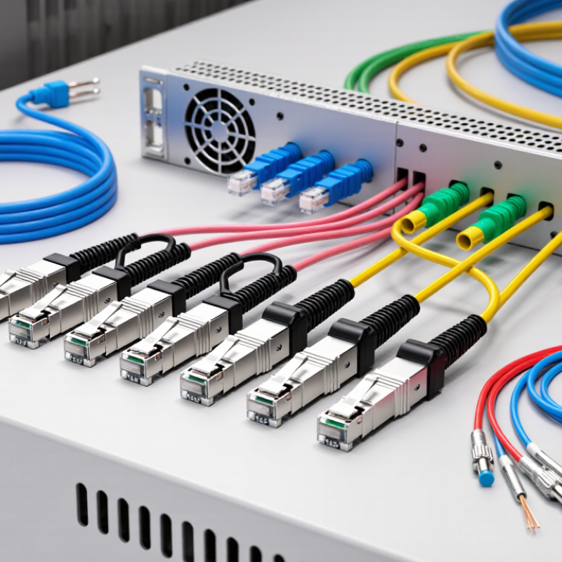
Select the connector required by the equipment, such as RJ45 for copper or LC, SC, or MPO/MTP-style interfaces for fiber. |
Perform a visual inspection and verify pinout or fiber polarity with a wire mapper, polarity tester, or optical light source and power meter. |
Replace connectors with broken latches, bent pins, loose ferrules, damaged clips, or unreliable retention. |
Use the same wiring scheme at both copper ends and confirm duplex or parallel-fiber polarity before connection. |
| Cable length |
Keep patch cords as short as practical. A balanced twisted-pair channel is commonly designed around a 100 m maximum channel, including patch cords. |
Measure length with a cable certifier or optical loss test set; do not rely only on the printed or ordered length. |
Replace or redesign routing when excess length creates loops, sharp bends, airflow obstruction, or accidental disconnection. |
Avoid unnecessarily long cords because they increase congestion and bend-management risk. |
| Copper visual inspection |
Check the jacket, strain relief, latch, contacts, and bend condition. |
Inspect before connection and after moves, adds, and changes. Confirm that the connector locks securely. |
Replace immediately if the jacket is crushed or cut, the latch is broken, contacts are corroded, or the plug does not seat firmly. |
Do not pull a copper cable by its plug or use it as a handle for equipment. |
| Fiber end-face cleanliness |
A clean, dry, and undamaged end face is required for low-loss optical connections. |
Inspect with a fiber microscope or inspection probe, clean with approved lint-free materials, and inspect again. |
Clean whenever a connector is disconnected or before testing. Replace if contamination cannot be removed or the end face is permanently damaged. |
Always keep dust caps on unused connectors and never touch the fiber end face. |
| Copper certification test |
Typical certification parameters include wire map, length, resistance, insertion loss, return loss, NEXT, PSNEXT, ACR-N, and DC loop resistance. |
Use a standards-based channel or permanent-link test setting and save the electronic test report. |
Troubleshoot termination, routing, connector damage, and external interference before replacing the cord; replace it if the cord is the confirmed failure point. |
Test after installation and after major changes, not only when a network fault occurs. |
| Fiber loss test |
Measure insertion loss against the calculated link budget and the applicable cabling standard. |
Use a light source and optical power meter; use an optical time-domain reflectometer when locating events or faults is necessary. |
Clean and retest first. Replace the patch cord if loss remains excessive or changes significantly when the cord is flexed gently. |
Record wavelength, reference method, test direction, and test limits with every result. |
| Bend radius and routing |
Follow the cable manufacturer’s minimum bend-radius instruction; avoid tight kinks, pinching, and sharp edges. |
Inspect cable paths in racks, trays, and cabinets. For fiber, retest optical loss after any suspected over-bending. |
Replace cables showing kinks, permanent deformation, crushed sections, or intermittent performance after movement. |
Use cable managers and hook-and-loop ties; avoid over-tightening ties around patch cords. |
| Environmental suitability |
Select indoor, plenum, riser, outdoor, or industrial construction according to the installation location and local fire requirements. |
Verify the cable jacket marking, temperature range, and regulatory requirements against the site specification. |
Replace cables exposed to incompatible heat, moisture, chemicals, ultraviolet radiation, or mechanical stress. |
Do not install an indoor-only cord in an outdoor, wet, high-temperature, or chemically aggressive environment. |
| Maintenance interval |
Perform visual checks during routine rack inspections and after every move, add, or change. Use formal recertification when required by the site policy or service agreement. |
Compare current test results with the installation baseline and review recurring alarms or error counters. |
There is no universal calendar-based replacement age; replace based on condition, failed testing, technology changes, or repeated faults. |
Maintain an asset record containing location, cable type, length, test date, result, and replacement history. |
| Standards and documentation |
Use the current applicable structured-cabling, connector, fire-safety, and installation standards specified for the project. |
Confirm tester calibration, test limits, adapter type, and report format before accepting the installation. |
Update documentation whenever a cord is replaced or a port is repatched. |
Common references include ISO/IEC 11801 and the applicable TIA cabling standards; always follow the project’s governing edition. |