How to Choose the Right Fiber Optic Patch Cable in 2026?

Choosing the right fiber optic patch cable in 2026 requires more than matching connector shapes. Network speed, installation distance, bend space, and equipment compatibility all influence the decision. A cable that performs well in a data center may be unsuitable for a crowded office cabinet. Tiny details matter. Connector polish, fiber type, jacket rating, and insertion loss can affect daily reliability.

This guide approaches selection from practical experience and recognized industry requirements. It considers single-mode and multimode fiber, LC, SC, and MPO connectors, along with duplex and simplex designs. It also explains how polarity, return loss, bend sensitivity, and transmission standards affect real installations. Technicians should verify manufacturer specifications and test results before purchasing. Product labels can look convincing, yet they may not reveal every limitation.

No checklist is flawless. Even experienced installers can overlook routing pressure behind a rack. A cable may meet its optical rating but fail in a tight pathway. That is why visual inspection, correct cleaning, and loss testing remain essential. The best fiber optic patch cable is not always the most expensive option. It is the one that fits the equipment, environment, and future upgrade plan without creating unnecessary risk. Measure twice. Connect once. This article will help readers compare cable constructions, connector choices, performance claims, and installation conditions with greater confidence. It will also challenge a common assumption: higher bandwidth alone does not guarantee a better cable choice. Reliability depends on the complete link.
How to Choose the Right Fiber Optic Patch Cable in 2026?

Fiber Optic Patch Cables: Definition, Structure, and Core Functions

How to Choose the Right Fiber Optic Patch Cable in 2026?

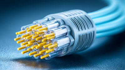
A fiber optic patch cable is a pre-terminated link for connecting network equipment, patch panels, and optical enclosures. Its structure is simple but precise. It includes a fiber core, cladding, protective coating, strength members, a jacket, and connectors. The core carries light signals, while the cladding keeps those signals contained. The jacket protects the cable from bending, moisture, dust, and daily handling.

Core functions include stable data transmission, equipment interconnection, and signal distribution across short or controlled pathways. Single-mode fiber suits long-distance links and high-capacity networks. Multimode fiber often fits shorter data-center connections. Connector polish, fiber count, jacket rating, and insertion loss also matter. A cable may look perfect but still perform poorly if its end face is dirty. That detail is easy to miss.

In practical installations, technicians should inspect and clean connectors before testing optical power and return loss.

Tips:

Match the cable type with the installed equipment, transmission distance, and environment. Check connector compatibility carefully. Allow gentle routing space; sharp bends can weaken performance. Keep protective caps fitted until installation. Record test results for future maintenance. A shorter cable is not always better. Leave enough length for safe movement, but avoid loose coils that obstruct airflow. Reconsider assumptions when the site changes. A design that worked in a quiet laboratory may struggle in a crowded cabinet.

How to Match Cable Types with Network Architecture and Equipment

How to Choose the Right Fiber Optic Patch Cable in 2026?

A patch cable should match the network architecture, not just the connector shape. Single-mode OS2 suits campus links, data center interconnects, and longer backbone runs. Multimode OM3 or OM4 fits shorter server-room connections using compatible multimode optics. For 400G and other parallel-optic links, MPO cables can reduce congestion. However, the transceiver must support the cable’s fiber count, polarity, and connector arrangement.

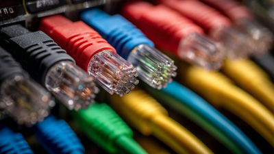
Match the cable to the equipment at both ends. LC duplex cables commonly connect switches, transceivers, and patch panels. MPO-to-LC breakout cables can connect parallel optics to separate duplex ports. Check UPC or APC polishing carefully; they are not automatically interchangeable. Also verify insertion loss, return loss, bend radius, jacket rating, and required length. A cable that is too long creates unnecessary slack and possible damage behind the rack.

Tips: Read the equipment datasheet before ordering. Confirm fiber mode, connector gender, polarity method, and optical budget. Label both ends during installation. Leave gentle service loops, not tight circles. I have seen clean-looking installations fail because one MPO polarity was reversed. This is an easy mistake. It deserves a second inspection. Testing with an optical power meter and light source provides stronger evidence than visual checking alone. Some specifications still seem clear until real rack spacing, airflow, and maintenance access expose their weaknesses.

Choosing Between Single-Mode, Multimode, Simplex, and Duplex Designs

Fiber choice in 2026 starts with distance, transceiver type, and port density. Single-mode fiber uses a narrow core, commonly 9/125 micrometers, for long-distance links. At 1310 or 1550 nanometers, it can support campus connections and data-center interconnects. Multimode fiber, often 50/125 micrometers, usually fits shorter indoor runs. It commonly operates around 850 nanometers and can simplify equipment selection. The easy mistake is judging by price alone.

Simplex cable contains one fiber strand and suits one-way transmission or systems using separate transmit and receive paths. Duplex cable contains two strands, supporting simultaneous two-way communication through one connection. It is the practical choice for most standard network links. Check the required polarity before installation. Label every strand. A mismatched transmit-receive arrangement can leave a healthy cable apparently inactive.

Connector shape, fiber type, jacket rating, and bend radius must match the equipment and pathway. Inspect end faces before insertion, because dust can create measurable loss. Test insertion loss after installation, not only continuity. In field work, a cable may pass a basic light check yet fail a high-speed link under temperature changes. I sometimes prefer extra length for service loops, although excessive slack can increase bends and clutter. Measure twice. Record the test results.

Evaluating Connectors, Fiber Grades, Lengths, and Installation Conditions

How to Choose the Right Fiber Optic Patch Cable in 2026?

Evaluating Connectors, Fiber Grades, Lengths, and Installation Conditions

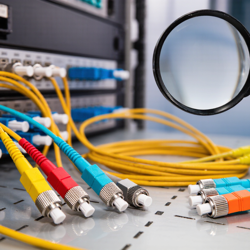
Choosing a fiber optic patch cable in 2026 starts with the connector, not the shopping list. In live racks, connector mismatch causes rushed adapters, extra loss, and fragile connections. LC suits dense panels, while SC offers a larger body for easier handling. MPO connectors support parallel links, but polarity and pin arrangement require careful verification. I have seen clean-looking assemblies fail because their connector keying was wrong. Check the equipment ports, latch direction, polish type, and rated insertion loss before ordering.

Match the fiber grade to the transceiver and distance. Single-mode OS2 is common for long campus or building links. OM4 supports high-speed multimode links over shorter indoor routes. OM5 may help selected SWDM designs, but it is not automatically better. Confirm wavelength, core type, and optical budget in the equipment documentation. A cable that fits physically can still produce unstable performance. Not always.

Measure the installed path, then add modest service slack. Excess length creates coils and pressure points inside a crowded cabinet. Too little length pulls connectors sideways. Respect the stated bend radius near trays, hinges, and vertical drops. For dusty rooms, choose suitable jackets and protect unused ports with caps. Inspect and clean both end faces before testing with a calibrated power meter and light source. Record polarity, length, test results, and installer observations. Measure twice. I still recheck measurements because a neat first estimate is sometimes wrong.

How to Choose the Right Fiber Optic Patch Cable in 2026?

Practical comparison of connectors, fiber grades, cable lengths, optical performance, and installation conditions. Always verify the equipment interface, link budget, polarity, and applicable site standards before ordering.
Application Requirement Recommended Fiber Grade Typical Wavelength Common Connector Options Typical Reach Guidance Recommended Cable Length Installation Conditions Selection Notes
Short Ethernet links in buildings OM3 multimode
50/125 µm
850 nm LC duplex, LC uniboot, or MPO/MTP-style array connector Commonly used for 10 Gb/s links up to approximately 300 m, depending on transceiver and channel design 1–10 m for equipment-to-equipment connections Indoor, controlled environment; standard PVC or low-smoke, zero-halogen jacket where required Suitable when the installed multimode infrastructure is OM3 and the transceiver specification supports it.
Higher-speed multimode data-center links OM4 multimode
50/125 µm
850 nm LC duplex for duplex links; MPO/MTP-style connector for parallel-fiber links Commonly used for 10 Gb/s links up to approximately 400 m; higher-speed reach depends on the optical standard and polarity scheme 1–15 m, with slack carefully managed High-density racks, overhead trays, patch panels, and frequent moves, adds, and changes Provides greater modal bandwidth than OM3 and is often preferred for demanding data-center applications.
Short-reach wideband multimode systems OM5 multimode
50/125 µm
850–953 nm for shortwave wavelength-division multiplexing applications LC duplex or MPO/MTP-style array connector Reach is application-specific and must be confirmed against the transceiver and channel standard 1–10 m Modern data-center environments designed for shortwave wavelength-division multiplexing Choose OM5 only when the active equipment and design specifically benefit from its wideband multimode characteristics; it is not automatically a replacement for OM4.
Long-distance single-mode backbone OS2 single-mode
9/125 µm
1310 nm or 1550 nm LC duplex, SC duplex, or simplex connectors as required by the equipment Suitable for kilometer-scale links; exact reach is determined by the optical interface, loss budget, and dispersion limits 2–30 m in racks; longer prefabricated assemblies may be used for structured cabling Campus, telecom, outside-plant, or long-distance indoor backbone installations Use when low attenuation and long reach are more important than short-reach multimode economics.
Legacy multimode replacement or extension OM2 multimode
50/125 µm
850 nm or 1300 nm LC duplex or SC duplex Reach varies by data rate; high-speed reach is generally shorter than OM3 or OM4 1–10 m Existing legacy installations where the installed fiber grade cannot be changed Do not select OM2 for a new high-speed build unless compatibility, distance, and transceiver requirements have been verified.
High-density switch or server connection OM4 or OS2, matched to the optical module 850 nm for many multimode systems; 1310/1550 nm for many single-mode systems LC duplex
Push-pull duplex LC options can improve rack density
Determined by the selected transceiver and structured cabling channel 0.5–3 m is commonly preferred to reduce congestion Dense racks, restricted bend space, and frequent patching Check connector latch style, polarity, duplex orientation, and minimum bend radius before installation.
Backbone patching between distribution panels OM3/OM4 for multimode systems; OS2 for single-mode systems Must match the installed fiber and active optics LC duplex, SC duplex, or MPO/MTP-style array connector Based on the complete channel length and optical loss budget 3–15 m, allowing service slack without excessive loops Patch panels, cabinets, cable trays, and structured cabling pathways Keep the patch cable type consistent with the permanent link and document polarity at both ends.
Outdoor or industrial deployment OS2 single-mode is common for long outdoor links; ruggedized multimode may suit short industrial links 1310 nm or 1550 nm for many single-mode systems Ruggedized LC, SC, or other connector type specified by the enclosure Project-specific; account for splice, connector, temperature, and environmental losses Use the shortest practical length while allowing routing and service loops Moisture, dust, vibration, ultraviolet exposure, temperature variation, or harsh industrial conditions Select an appropriate jacket, connector protection, ingress rating, and temperature range; ordinary indoor patch cords may be unsuitable.
Frequent reconfiguration and maintenance Fiber grade must match the existing link: OM3/OM4 for multimode or OS2 for single-mode Determined by the installed optical system LC is commonly convenient for dense patching; SC may be easier to handle in lower-density panels Do not exceed the channel design distance or loss budget Choose a length that avoids tension and excessive slack; commonly 1–5 m in racks Frequent insertion and removal, limited workspace, and high cable density Consider uniboot polarity, bend-insensitive fiber, pull tabs, latch protection, and clear labeling.
Sensitive or tight cable-routing areas OS2, OM3, OM4, or OM5 with bend-insensitive construction where available and compatible Depends on fiber grade and transceiver LC duplex or compact array connector Must remain within the optical standard and link budget Measure the route accurately; avoid ordering excessive spare length Sharp rack transitions, high-density enclosures, and constrained pathways Respect the manufacturer’s static and dynamic bend-radius ratings; never kink, crush, or tightly coil the cable.

Checking Performance, Standards, Durability, and Future Network Needs

How to Choose the Right Fiber Optic Patch Cable in 2026?

Performance begins with the network, not the cable label. Check single-mode or multimode requirements, connector type, polarity, and insertion loss. A short link can still fail when poor end-face cleaning causes reflection. The ITU Facts and Figures 2023 report counted 5.4 billion internet users, representing 67% of the global population. More users mean heavier traffic and less tolerance for unstable links.

Standards provide a safer selection path. Match the assembly with ISO/IEC 11801 and the relevant TIA-568.3 requirements. For dense cabinets, consider bend-insensitive fiber compliant with ITU-T G.657.A2. Verify test results at the operating wavelength, not only at 850 nanometers. Inspect the connector under magnification. Tiny scratches matter. A visual check is not enough.

Durability deserves equal attention. Look for pull strength, repeated mating performance, temperature range, and jacket suitability. Indoor PVC is not appropriate for every pathway. Tight routing can create hidden attenuation months later. The OECD Digital Economy Outlook 2024 identifies rising data demand as a continuing pressure on communications infrastructure. Choose extra fiber counts and higher-speed compatibility where replacement access is difficult. My checklist is not perfect. I once focused too heavily on optical loss and overlooked bend radius near a rack hinge. That small detail later complicated maintenance. Future-ready design needs measured performance, documented standards, and room for human error.

x